


 +86-13516964051


News
Aluminum alloy low
0102030405
Aluminum Alloy Die-Casting Mold Design and Manufacturing
2025-09-26
Aluminum Alloy Die-Casting Mold Design and Manufacturing
I. Introduction: Molds - The "Invisible Engine" of Aluminum Alloy Die-Casting
In the aluminum alloy die-casting industry, molds are like "invisible engines," directly determining product precision, performance, and production efficiency. An automotive parts company once experienced a die-casting pass rate of only 65% due to improper mold gate design. Later, through mold optimization, the pass rate jumped to 98%. This data clearly demonstrates that professional mold design and manufacturing is the core moat of a company's competitiveness.
Aluminum alloy die-casting molds must simultaneously withstand the impact of high-temperature molten aluminum, the loads of high-pressure forming, and the wear of cyclic production. Their design and manufacturing involve the intersection of multiple disciplines, including materials science, thermodynamics, and mechanical engineering, requiring meticulous control of technical details that can be described as a "millimeter-level test."
II. Aluminum Alloy Die-Casting Mold Design: Precise Transformation from Requirements to Drawings
Mold design is a critical step in the "source control" process, aiming to achieve the three key objectives of "functional adaptation, process optimization, and cost balance." It focuses on the following five key elements:
1. Cavity Design: The "Core of Molding" that Matches Product Characteristics
The cavity is the space where the molten aluminum alloy is finally formed. Its design must integrate both product structure and die-Casting Process dimensions:
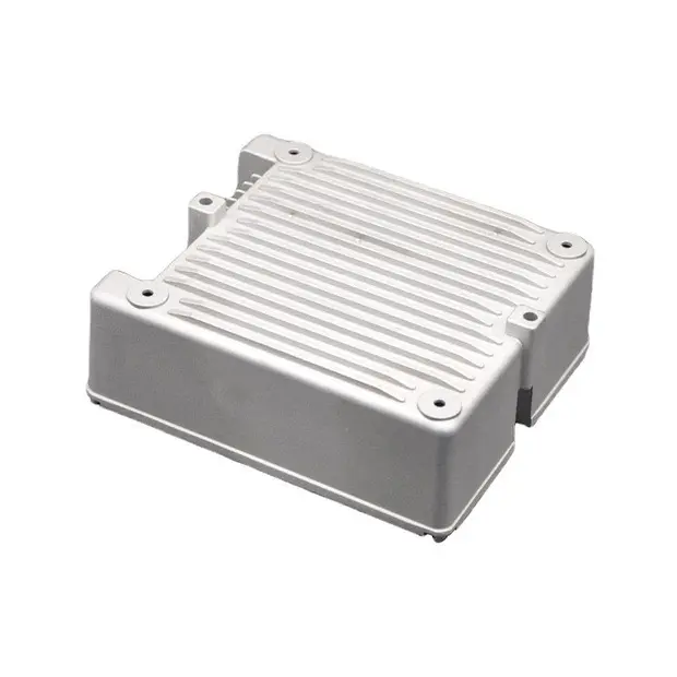
Structural Adaptation: For thin-walled parts (such as electronic housings, with a wall thickness of 0.8-1.5mm), a "shallow cavity + multiple gates" design is employed to reduce filling resistance. For complex structural parts (such as automotive transmission housings), parting surface optimization is employed to avoid undercuts and reduce demolding difficulty.
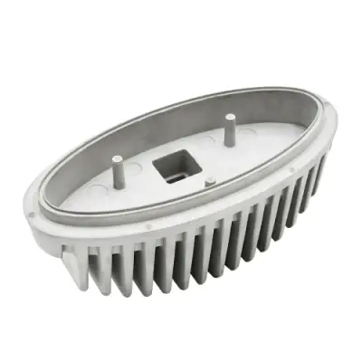
Precision Allowance: Taking into account the cooling shrinkage of aluminum alloy (typically 0.5%-1.2%), precise allowance is reserved in the cavity dimensions while ensuring a surface roughness of Ra ≤ 0.8μm, minimizing subsequent processing. In a new energy vehicle motor end cover project, the die-cast part initially developed porosity defects due to an overly shallow vent groove design. The vent groove depth was subsequently adjusted from 0.1mm to 0.15mm, and three auxiliary vent channels were added, completely resolving the porosity issue.
2. Gating System: The "Vascular Network" that Ensures Molten Aluminum Flow
The gating system includes gates, runners, vent grooves, and overflow troughs. Its design directly impacts the filling efficiency of the molten aluminum:
Gating Selection: Fan-shaped gates are preferred for large structural parts to ensure even distribution of the molten aluminum; pin-shaped gates are used for small, Precision Parts to reduce gate residue.
Runner Optimization: A "constant cross-section runner" design is used to minimize pressure loss during the flow of the molten aluminum. Rounded transitions are used at runner bends to reduce eddy currents.
Venting Design: Vents should be located in the final area of molten aluminum filling, such as at the end of the cavity or at the intersection of ribs. The width of the vent grooves is typically 5-10mm to ensure adequate evacuation of gases from the cavity.
3. Cooling System: The "Temperature Control Center" for Temperature Balance
During the aluminum alloy die-casting process, mold temperatures must be maintained between 200-300°C. The design of the cooling system is crucial:
Water channel layout: Following the principle of "close to the cavity, evenly distributed," the distance between the water channel and the cavity surface is maintained at 15-25mm. For areas with concentrated heat dissipation (such as near the gate), denser or spiral water channels are used.
Temperature Control: Through precise control of inlet water temperature and flow rate, the temperature difference between different areas of the mold is maintained at ≤20°C, preventing product deformation or cracking caused by uneven temperatures.
In a laptop casing project, symmetrical water channels on both sides of the mold, combined with an intelligent temperature control system, reduced product warpage from 0.5mm to within 0.15mm.
4. Ejector System: The "Actuator" for Smooth Demolding
The ejector system must ensure uniform force distribution during demolding to avoid damage or deformation.
Ejector Pin Placement: Prioritize placement of ejectors in areas with thicker and stronger product walls. Ejector pin diameter is calculated based on product weight; generally, the area should be ≥ 10 mm² per 100 g of product.
Ejector Speed: Utilize a "staged ejection" mode, with an initial low ejection speed (5 mm/s) to prevent product adhesion to the cavity, and a later high ejection speed (15 mm/s) to improve production efficiency.
5. Material Selection: The "Basic Guarantee" that Determines Mold Life
Mold materials must meet the requirements for wear resistance, heat resistance, and toughness. Common materials and their applicable applications are as follows:
H13 mold steel: Suitable for precision parts with medium to high production volumes (over 100,000 molds). It offers excellent thermal fatigue resistance and can achieve a hardness of 42-48 HRC after quenching. SKD61 mold steel: A cost-effective choice for small to medium-sized production runs (50,000-100,000 molds), with a hardness of 38-42 HRC and excellent machinability.
Pre-hardened steel (such as 718H): Requires no post-Heat Treatment and is suitable for rapid mold trials or low-volume production. Hardness is 33-37 HRC.
III. Aluminum Alloy Die-Casting Mold Manufacturing: Precision Implementation from Drawing to Finished Product
If design is the "blueprint," manufacturing is the "implementation." Multiple precision processes are required to ensure mold accuracy and performance. The core processes include:
1. Die Blank Machining: Laying the Foundation for Precision
The die blank is formed using a forging process to reduce internal porosity and loose defects. The Machining Process is as follows:
Rough Machining: Milling and lathes are used to machine the die blank's outer shape and cavity contours, leaving a 5-10mm machining allowance.
Heat Treatment: The die blank undergoes quenching and tempering (quenching and high-temperature tempering) to achieve a uniform metallographic structure and improve the material's overall mechanical properties.
2. Cavity Precision Machining: Pursuing Micron-Level Precision
Cavity machining is the core of the manufacturing process. Common processes include:
CNC milling: Semi-finishing using a high-speed machining center (speed ≥15,000 rpm), ensuring a cavity dimensional accuracy of ±0.02mm.
Electrical Discharge Machining (EDM): For complex cavities or small structures (such as narrow slits and deep holes), EDM is used to achieve surface roughness of up to Ra 0.4μm and dimensional accuracy of ±0.005mm.
Wire Cutting Machining (WEDM): Used for machining flat or curved surfaces such as parting surfaces and inserts, with a cutting accuracy of ±0.003mm.
In a precision connector mold project, the combined process of "CNC rough milling → EDM finishing → WEDM parting surface machining" achieved a cavity dimensional tolerance of within ±0.008mm, meeting product assembly requirements.
3. Surface Treatment: Improving Mold Performance and Lifespan
Surface treatment can significantly improve a mold's wear resistance and mold release properties. Common processes include:
Nitriding: Forms a 5-10μm nitride layer on the mold surface with a hardness of 800-1000 HV, improving mold wear resistance and extending mold life by over 30%.
Coating: Utilizing PVD (Physical Vapor Deposition) technology, coatings such as TiN and CrN are applied to the mold surface to reduce adhesion between the molten aluminum and the mold while also improving heat resistance.
4. Assembly and Commissioning: Achieving the "Last Mile" of Design Functionality
Assembly and commissioning must be carried out strictly in accordance with the design drawings. Key steps include:
Component Assembly: Precisely assemble components such as the cavity, core, and ejector mechanism, ensuring clearances between all moving parts are ≤0.01mm.
Mold Trial Adjustment: Observe the molten aluminum filling and product molding quality during trial molds, and make targeted adjustments to parameters such as gate size, cooling water flow rate, and ejector speed until the product meets quality standards. Common Problems and Solutions During Mold Trial:
Problem Type
Cause
Solution
Product Shortage
Gate Too Small, Insufficient Pressure
Enlarge Gate, Increase Die Casting Pressure
Surface Sink Marks
Uneven Cooling, Short Holding Time
Optimize Cooling Water Channels, Extend Holding Time
Difficulty Demolding
Insufficient Draft Angle, Surface Sticking
Increase Draft Angle, Apply Release Agent
IV. Mold Quality Control and Lifespan Management: Achieving Long-Term Stable Production
High-quality molds require not only precise design and manufacturing but also a comprehensive quality control and lifespan management system:
1. Full-Process Quality Inspection
Design Phase: Use CAE (Computer-Aided Engineering) software (such as Moldflow) to perform simulations and analyses of filling, cooling, and warpage to identify design flaws early.
Manufacturing Phase: Use a coordinate measuring machine to check cavity dimensional accuracy, a hardness tester to test material hardness, and ultrasonic testing to detect internal defects. Mold Trial Phase: Test molds undergo dimensional measurement, mechanical property testing (tensile strength, elongation), and visual inspection to ensure they meet customer requirements.
2. Mold Life Extension Strategies
Daily Maintenance: Clean the mold surface after each production run, inspect moving parts like ejector pins and guide pins for wear, and re-lubricate promptly.
Regular Maintenance: After every 5,000 molds, perform a complete disassembly and inspection of the mold, replace worn parts, and perform a nitriding or re-coating.
Storage Management: Idle molds should be coated with anti-rust oil and stored in a dry, ventilated environment to prevent moisture and rust.
An automotive parts company established a "Mold Full Lifecycle Management System" to track data from mold design, manufacturing, use, and maintenance in real time. This has increased the average mold life from 80,000 to 120,000 cycles, reducing mold replacement costs.
V. Conclusion: Driving the Upgrade of the Aluminum Alloy Die-Casting Industry with Precision Molds
Driven by high-end manufacturing sectors such as new energy vehicles, 5G communications, and aerospace, aluminum alloy die-casting products are evolving toward greater precision, thinner weight, and higher performance, placing higher demands on mold design and manufacturing.
From micron-level cavity design to millimeter-level control in manufacturing, from precise temperature control in cooling systems to full-process tracking of lifespan management, meticulous attention to detail is driving quality upgrades in the aluminum alloy die-casting industry. In the future, with the in-depth application of AI simulation and 3D printing technologies in the mold industry, aluminum alloy die-casting molds will achieve breakthroughs in "smarter design, more efficient manufacturing, and longer lifespans," providing even stronger support for high-end manufacturing.