+86-13516964051


Choosing a Brake Vacuum Pump in 2026 is not just a matter of matching a part number. The right pump must supply dependable vacuum under the conditions your vehicle actually faces. Consider the brake booster’s demand, engine type, pump drive, and expected duty cycle. An electric pump may suit an engine with limited manifold vacuum, while a mechanically driven unit may fit another setup. Compatibility comes first.
Small details matter. Check the specified vacuum level and flow rate, along with voltage, connector type, mounting points, and available space. A pump that fits physically may still deliver too little vacuum or draw too much current. That matters. Review operating-temperature limits, noise, sealing materials, and service requirements, especially if the vehicle works in stop-and-go traffic or cold weather. Compare the manufacturer’s specifications with the vehicle’s service information, and confirm fitment before ordering.
Do not assume a weak brake pedal always means the pump has failed. A leak, damaged hose, faulty check valve, or booster issue can produce similar symptoms. Not always obvious. A basic inspection and vacuum test can help identify the real cause; a qualified technician should assess uncertain or safety-critical faults. This guide explains how to compare pump types, evaluate performance, check installation needs, and judge long-term reliability. The choice may involve trade-offs between cost, noise, and service life. No single model is best for every vehicle. A careful match is safer than relying on a broad product claim.
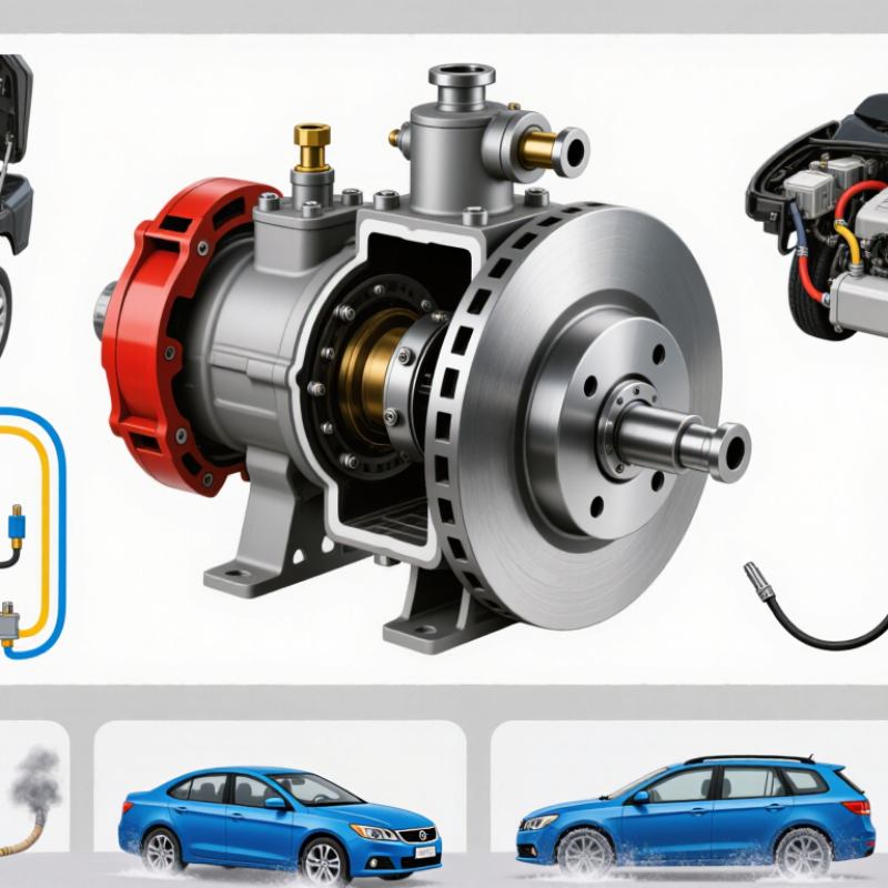
How to Choose a Brake Vacuum Pump in 2026? Start with the vehicle’s electrical system. Passenger cars commonly use 12 V systems, while many heavy vehicles use 24 V. Bosch Automotive Handbook (10th edition) describes these conventional voltage architectures. In practice, a 12 V battery may read about 12.6 V at rest and roughly 13.5–14.8 V while charging; a 24 V system operates at approximately twice those levels. These are typical values, not a substitute for checking the vehicle’s service data.
A pump with the wrong voltage can fail to operate correctly or may be damaged. Check the vehicle label, wiring diagram, and pump specification before purchase. Also confirm connector type, current draw, mounting space, and whether the vehicle uses an electric or engine-driven vacuum source. A common oversight is choosing by vehicle size alone. Two heavy vehicles can use different pump configurations, depending on their braking and electrical systems. Match the pump to the actual system.
Tips: Verify the rated voltage and polarity, then compare the pump’s current demand with the circuit rating. If the label is unclear, use a multimeter and consult the service manual. Don’t guess.
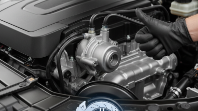
Start with the vehicle’s specified vacuum level, expressed as kPa below local atmospheric pressure. A vacuum gauge at the booster line can show how quickly pressure recovers after several pedal applications. Record the lowest reading and recovery time, not just a stable reading at idle. Conditions matter. Engine temperature, hose length, leaks, and altitude can change the result.
Then compare pump performance at the vacuum level your system actually needs. Check flow in L/min at that operating point; a free-air flow rating alone may look impressive but say little about performance under load. Allow capacity for repeated braking and normal system leakage, while checking the pump’s duty-cycle and thermal limits. I have seen selections based on peak figures alone, and that can leave little reserve. Still, measurements can be messy, so repeat them before deciding.
How to Choose a Brake Vacuum Pump in 2026?
Choose a brake vacuum pump by matching its duty cycle to the vehicle’s actual brake-assist demand. The IEA’s Global EV Outlook 2024 reports nearly 14 million electric cars were sold in 2023, around 18% of global car sales. As electric vehicles lack a conventional engine vacuum source, their pumps must maintain assist during repeated braking and engine-off operation. That market figure signals a shift, not a universal pump specification.
Check booster volume, expected brake applications, leakage allowance, and recovery time. Then assess cold starts, high temperatures, altitude, and stop-and-go routes. A pump’s maximum vacuum reading alone can mislead; airflow and recovery under load matter too. Cold starts matter. Test the system at the hardest expected condition, and confirm it restores vacuum quickly between applications. NHTSA’s FMVSS No. 135 braking tests emphasize repeated-stop performance, reinforcing why a single static reading is not enough. Exact demand varies by vehicle, so validate against the booster and system requirements.
Tips: Log vacuum recovery time during repeated pedal applications, including after a cold soak. Leave margin for wear and small leaks, but avoid oversizing without need; excess cycling can add noise, heat, and electrical load. Do not guess. A neat test plan beats a confident estimate, though real-world driving still brings surprises.
Match pump duty cycle to brake-assist demand and operating conditions.
These ranges are initial planning estimates, not universal specifications. Frequent braking, high vehicle load, vacuum leaks, and hot operating conditions can increase pump run time. Choose a pump rated for at least the upper end of the expected duty-cycle band, and confirm the selection using measured vacuum demand and the pump’s ratings at the actual temperature and supply voltage.
A brake vacuum pump should be matched to its vehicle’s electrical and mounting environment, not just its nominal voltage. ISO 16750-2:2023 provides test methods for electrical loads, including supply variation, interruptions, reverse voltage, and transient events. Ask for test results against the vehicle’s specified profile. A “12-volt” label alone says little about performance during cranking dips or voltage spikes. Check operating and storage limits, connector sealing, and protection against polarity errors. Real installations are messier.
Use ISO 16750-4:2023 to assess climatic loads, such as temperature exposure and humidity, against the pump’s actual installation zone. A unit near a hot engine may face a different profile from one mounted in a cooler compartment. The IEA’s Global EV Outlook 2024 projected about 17 million electric-car sales that year, more than one-fifth of global sales. That shift makes electrical compatibility across vehicle architectures worth checking carefully, though it does not replace vehicle-specific testing. Compare declared test levels with measured supply conditions, and request traceable reports identifying the setup, duration, and acceptance criteria. I would still leave margin for aging connectors and imperfect grounds; standards cannot capture every installation.
Selecting a brake vacuum pump in 2026 starts with the vehicle, not the pump’s catalog rating. FMVSS 135 and UNECE Regulation No. 13 address vehicle-level braking, but the applicable requirements depend on vehicle category and target market. Confirm the correct compliance pathway before setting pump targets. The pump is one component. A component-level test alone cannot establish that the complete vehicle meets braking requirements.
Evaluate vacuum availability and recovery alongside brake performance. Check repeated pedal applications, cold starts, low-voltage operation, and realistic vacuum leaks. Record how quickly assistance returns after demand, and whether warning signals behave as intended. Test the finished vehicle using the procedures and conditions applicable to its approval program. A neat bench result can still mislead. Tire condition, vehicle load, brake calibration, and control-system behavior can all affect results.
For a useful selection, compare pump capacity, response time, duty cycle, electrical demand, noise, and durability against measured vehicle needs. Keep test records traceable to the vehicle configuration and software version. If results vary between test runs, investigate before treating the highest reading as representative. One uncomfortable detail: more vacuum capacity is not automatically better. Packaging, heat, power draw, and system integration still matter.
| Selection Dimension | What to Verify | Evidence or Measurement | Selection Guidance |
|---|---|---|---|
| Applicable regulation and vehicle category | Identify the vehicle category, sales market, and applicable regulatory edition. FMVSS No. 135 and UNECE Regulation No. 13 have different scopes and test procedures; UNECE R13-H is a separate regulation for passenger-car braking. | Vehicle classification, target-market requirements, and the applicable regulation and amendment series. | Confirm regulatory applicability before specifying the pump. Do not assume that a pump approval or component test demonstrates vehicle-level compliance. |
| Brake-system vacuum demand | Determine the vacuum level and usable reserve required by the complete brake-assist system, including the booster, hoses, valves, and any reservoir. | Vacuum pressure measured at the relevant system location during defined brake-use and recovery conditions. | Set requirements from the vehicle’s brake-system design and validated test conditions; there is no single pump vacuum target that applies to every vehicle. |
| Pumping capacity and recovery time | Check the pump’s evacuation performance at the operating vacuum range, not only its free-air flow rating. | Supplier performance curves or test data showing flow versus inlet pressure, plus vehicle-level vacuum recovery measurements. | Choose capacity that meets the vehicle’s recovery needs across the intended operating range. Validate with the actual system volume and plumbing. |
| Repeated brake applications and reserve | Assess how vacuum reserve changes during repeated brake applications, including the conditions specified by the applicable vehicle test plan. | Time-history data for vacuum level, warning indication if fitted, and brake performance during application and recovery sequences. | Verify the complete system under representative and worst-case conditions. A pump’s nominal rating alone does not establish adequate reserve. |
| Electrical supply and control | Confirm compatibility with the vehicle electrical system, including operating voltage, current draw, startup behavior, control logic, and fault response. | Voltage and current measurements during startup, steady operation, low-voltage conditions, and relevant fault tests. | Check that wiring, protection, control thresholds, and diagnostics are suitable for the vehicle. Include pump operation in system-level fault analysis. |
| Duty cycle and thermal capability | Evaluate whether the pump can withstand the expected operating frequency and ambient and under-hood temperature conditions. | Duty-cycle limits, thermal test results, temperature measurements, and endurance data for the intended installation. | Use performance and durability data for the real operating profile. Avoid relying on intermittent-duty data for a continuous or frequently cycling application. |
| Installation and environmental exposure | Review mounting orientation, available space, hose routing, vibration, water and dust exposure, acoustic requirements, and service access. | Packaging review, installation instructions, environmental test data, and vehicle-level noise or vibration checks where applicable. | Confirm that installation does not introduce leaks, restrictions, excessive noise, or exposure beyond the pump’s documented limits. |
| System integrity and leak testing | Check the assembled vacuum circuit for leakage, pressure losses, and correct operation of valves and connections. | Leak-test results and vacuum-decay or recovery measurements on the completed vehicle system. | Investigate leaks and flow restrictions before increasing pump capacity; they can reduce assist availability and alter recovery performance. |
| Failure behavior and warnings | Assess the effects of pump, power-supply, control, hose, and valve failures on braking performance and driver warnings. | Fault-injection results, warning-system checks, and brake-performance data with relevant assist faults present. | Verify the vehicle’s designed failure response against applicable requirements. A pump component test cannot replace vehicle-level failure testing. |
| Compliance verification plan | Test the complete vehicle using the procedures and conditions required by the applicable regulation and certification process. | Vehicle test reports covering relevant braking performance, assist-system behavior, and required test conditions. | Use the pump as one element of the brake system. Compliance is determined for the vehicle under the applicable regulatory procedures, not from pump selection alone. |
| Supplier documentation | Request traceable specifications for performance, electrical characteristics, operating limits, durability, and installation requirements. | Datasheets, test methods, revision-controlled drawings, and quality or change-control documentation. | Compare data measured under equivalent conditions and confirm that the delivered configuration matches the validated design. |
| Engineering note | The selection checks above are engineering guidance, not a substitute for the current legal text, regulatory interpretation, or vehicle certification testing. Confirm the applicable FMVSS or UNECE requirements for the specific vehicle and market. | ||